What This Guide Covers
Gate location is one of the most critical decisions in injection molding, yet it’s often overlooked until problems appear in production. Where you position the gate—the point where molten plastic enters the mold cavity—directly impacts part appearance, strength, dimensional accuracy, and manufacturing efficiency.
In this guide, you’ll learn:
- How gate placement affects plastic injection molding quality
- Common gate location mistakes and their consequences
- Strategic gate positioning for different applications
- How to work with plastic injection molding companies on gate design
- Practical guidelines for optimal results
Whether you’re developing automotive plastic moulage par injection parts or working with a custom plastic injection molding service for consumer products, understanding gate location principles will improve your outcomes and reduce costly revisions.
Understanding Gates in Injection Molding
After over a decade of designing molds and optimizing injection molding processes, I’ve seen gate location decisions make or break product success. The gate is literally where everything begins—it’s the entry point through which molten plastic flows from the injection molding machine into your part cavity.
Last year, a medical device client came to us with persistent weld line problems on a critical component. Their previous plastic injection molding manufacturer had placed the gate in the “convenient” location for mold making, not optimal for part quality. We relocated the gate to the part’s geometric center, and the weld lines moved to non-critical areas. Problem solved without changing a single other variable.
But I’ve also witnessed the reverse. An automotive client once insisted on a specific gate location for aesthetic reasons, overriding our engineering recommendations. The result? Warpage issues that required three months of troubleshooting and ultimately a gate relocation—exactly where we’d originally suggested. That stubbornness cost them $45,000 and delayed production by 14 weeks.
Gate location in plastic injection molding affects:
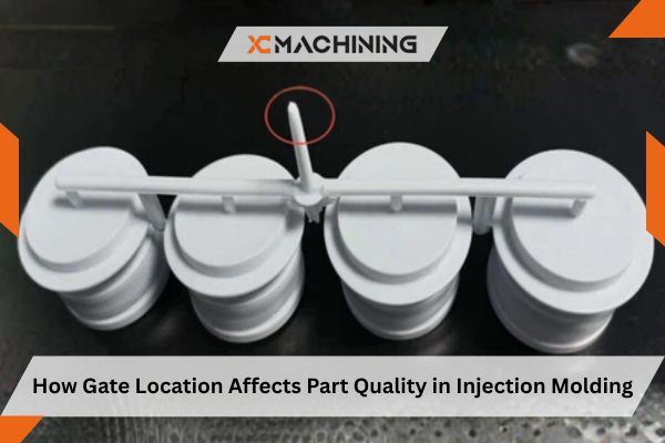
- Visual appearance and gate vestige size
- Part strength and structural integrity
- Dimensional accuracy and warpage
- Fill pattern and potential defects
- Cycle time and manufacturing cost
- Mold complexity and maintenance
Why Gate Location Matters So Much
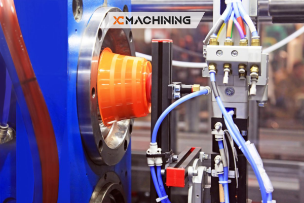
When you press “start” on a plastic injection molding machine, molten plastic (typically heated to 400-550°F depending on the resin) injects through the gate at high pressure and velocity. This plastic flows through the cavity, pushing air ahead of it, cooling as it travels, and solidifying into your part shape.
The gate location determines:
Flow path and distance: Plastic cools as it flows. Longer flow paths mean cooler plastic reaching far areas, potentially causing short shots or weak weld lines.
Pressure distribution: Pressure drops as plastic travels. Areas farthest from the gate receive lowest pressure, affecting part density and dimensions.
Fill pattern: Gate position controls how plastic fills the cavity. Poor placement creates turbulence, traps air, and causes aesthetic defects.
Weld line formation: When flow fronts meet, they create weld lines. Gate location determines where these occur and how strong they are.
Orientation effects: Plastic molecules align with flow direction, creating directional strength properties. Gate location controls this orientation pattern.
Common Gate Types and Their Applications
Different gate types suit different applications in the plastic injection molding industry. Here’s what you need to know:
Gate TypeSizeRemovalBest ForCommon Issues
Edge Gate 0.040-0.120″ Manual trim Large flat parts, prototypes Visible gate mark
Sub Gate 0.020-0.040″ Auto-shear High-volume production Restricted flow
Hot Tip 0.060-0.100″ Manual trim Thick-walled parts Requires hot runner
Pin Point 0.015-0.030″ Auto-shear Cosmetic surfaces Flow restrictions
Fan Gate Variable Manual trim Wide, thin parts Gate vestige
Film Gate Very thin Minimal Thin-walled parts Limited to edges
When working with precision plastic injection molding services, discuss gate type selection early in the design process. The gate type determines where you can physically locate gates on your part.
Strategic Gate Location Principles
Based on experience with thousands of plastic injection molding projects across automotive, medical, and consumer sectors, here are the fundamental principles:
1. Gate at the Thickest Section
Pourquoi c'est important : Molten plastic flows more easily through thick sections than thin ones. Gating at the thickest point ensures plastic can flow into thinner areas before excessive cooling occurs.
Real example: I designed a mold for an ABS plastic injection molding automotive dashboard component with varying wall thickness (2mm to 6mm). By gating at the 6mm boss, we achieved complete fill with no short shots. When the client requested moving the gate to a 2mm edge for aesthetics, we got incomplete fill and had to increase injection pressure by 40%, which caused flash in other areas.
Application guidelines:
- Identify thickest section in part geometry
- Gate there when possible
- If multiple thick sections exist, consider multiple gates
- Thick sections act as reservoirs feeding thinner areas
2. Minimize Flow Distance
Pourquoi c'est important : Plastic cools as it travels. Excessive flow distance causes cold plastic reaching far areas, leading to short shots, weak weld lines, and excessive injection pressure requirements.
Rule of thumb: Maximum flow-to-thickness ratio should be 150:1 for general plastics, 100:1 for filled materials.
Practical calculation:
- Part with 2mm wall thickness
- Maximum recommended flow distance: 2mm × 150 = 300mm (11.8 inches)
- Beyond this, consider additional gates
Real example: We had a 500mm × 300mm electronics enclosure (2mm wall) where the client wanted a single center gate for symmetry. Flow distance exceeded 250mm in corners—far beyond the 300mm maximum. We added four gates instead, dramatically improving fill and reducing cycle time by 18%.
3. Control Weld Line Location
Pourquoi c'est important : Weld lines occur where flow fronts meet. These are inherently weak points and often visible. Smart gate placement controls where weld lines form.
Strategy:
- Position gates so weld lines fall in non-critical areas
- Avoid weld lines on load-bearing features
- Keep weld lines away from visible surfaces
- Use flow analysis to predict weld line formation
Real example: For automotive plastic injection molding automotive parts like mirror housings, we strategically gate to push weld lines to the mounting boss area (hidden) rather than the visible exterior surface. This simple gate relocation saved the client from secondary painting operations.
4. Consider Part Ejection
Pourquoi c'est important : The gate creates a connection point that affects how parts eject from the mold. Poor gate location can cause sticking, requiring excessive ejection force that damages parts.
Guidelines:
- Gate opposite the primary ejection direction when possible
- Avoid gating on deep ribs or bosses that resist ejection
- Consider gate vestige removal method
- Balance cosmetic requirements with ejection needs
5. Maintain Symmetry for Thin-Walled Parts
Pourquoi c'est important : Asymmetric fill in thin-walled parts causes differential shrinkage and warpage. Symmetric gating creates balanced flow patterns.
Real example: We produced thin-walled containers (0.8mm wall) for a packaging client. Initial single-gate design caused significant warpage. Switching to a four-gate symmetric pattern reduced warpage from 2.4mm to 0.3mm—acceptable for the application.
Applications :
- Critical for thin-walled parts (<1.5mm)
- Essential when tight flatness tolerances required
- Important for parts with large surface areas
- Consider multi-gate layouts for balance
Common Gate Location Mistakes
After consulting with dozens of plastic injection molding companies and reviewing hundreds of molds, these mistakes appear repeatedly:
Mistake #1: Gating for Mold Maker Convenience
The problem: Choosing gate location based on what’s easiest to machine rather than what’s best for part quality.
The consequence: Suboptimal fill patterns, defects, and quality issues that appear only in production.
The solution: Make gate decisions based on part requirements first, then work with your plastic injection molding manufacturer to implement the optimal location even if it adds mold complexity.
Mistake #2: Ignoring Flow Analysis
The problem: Making gate location decisions by intuition rather than using simulation software to predict flow behavior.
The consequence: Unexpected defects, weld lines in critical areas, and costly mold revisions.
The solution: Invest in flow analysis before cutting steel. Most custom plastic injection molding services offer this, and it costs far less than mold modifications.
Mistake #3: Single Gate When Multiple Gates Needed
The problem: Trying to fill large or complex parts from a single gate to save on mold cost.
The consequence: Long flow paths, excessive pressure requirements, cold plastic reaching extremities, poor part quality.
The solution: Add gates when flow analysis indicates problems. The added mold cost is minimal compared to production issues.
Mistake #4: Gating on Cosmetic Surfaces
The problem: Placing gates where vestige will be visible on Class A surfaces.
The consequence: Every part shows gate marks, requiring secondary operations or customer complaints.
The solution: Gate on hidden surfaces, parting lines, or non-visible areas. Use submarine gates that break cleanly if needed on visible areas.
Mistake #5: Not Considering Material Properties
The problem: Using the same gate strategy for all materials without accounting for their different flow characteristics.
The consequence: Materials with poor flow (like filled plastics) fail to fill properly with gate locations that work fine for unfilled resins.
The solution: Adjust gate strategy based on specific material. Filled materials, fiber-reinforced plastics, and high-viscosity resins need different approaches than commodity plastics.
Gate Location Guidelines by Application
Here’s practical guidance based on common plastic injection molding applications:
Automotive Plastic Injection Molding
Interior components (dashboards, door panels):
- Gate at mounting bosses or hidden surfaces
- Push weld lines to non-visible or low-stress areas
- Consider texture effects on gate vestige visibility
- Multiple gates common for large parts
Under-hood components:
- Gate at thickest sections for high-temperature materials
- Minimize weld lines due to structural requirements
- Consider fiber orientation for reinforced plastics
- Heat resistance trumps cosmetic concerns
Exterior components (bumpers, grilles):
- Gate behind mounting areas or inside surfaces
- Critical weld line control for Class A surfaces
- Often require multiple gates for size
- Balance fill pattern with aesthetic requirements
Électronique grand public
Housings and enclosures:
- Gate at internal bosses or mounting points
- Hide gates on parting lines when possible
- Control flow to minimize internal stresses
- Consider snap fit feature interaction with flow patterns
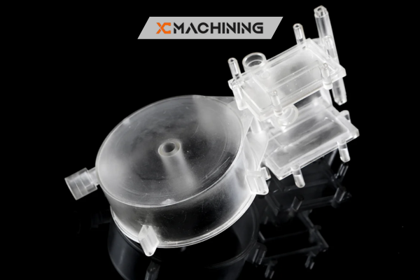
Transparent parts:
- Gate location critical for optical quality
- Minimize weld lines in viewing areas
- Control flow velocity to prevent jetting
- Often requires hot runner systems
Medical Device Components
Precision components:
- Gate for dimensional accuracy priority
- Minimize internal stress through balanced fill
- Control orientation for strength requirements
- Document gate location for validation
Biocompatible parts:
- Gate removal must leave clean surface
- Avoid gates on patient-contact surfaces
- Consider sterilization effects on gate area
- Often use valve gates for clean break
Working with Plastic Injection Molding Services
When partnering with a plastic injection molding company or plastic injection molding manufacturer, clear communication about gate location is essential.
During Design Review
Questions to ask:
- Where do you recommend gating this part?
- What gate type do you suggest and why?
- Have you run flow analysis?
- What defects might we expect with this gate location?
- Are there alternative gate locations worth considering?
Information to provide:
- Critical dimensions and tolerances
- Cosmetic requirements (Class A surfaces)
- Load-bearing areas and stress points
- Acceptable gate vestige locations
- Production volume expectations
Red Flags to Watch For
Be cautious if your plastic injection molding service:
- Can’t explain gate location rationale
- Dismisses your gate location concerns
- Won’t run flow analysis before committing
- Suggests gating purely for mold cost savings
- Has no experience with your material-application combination
Design Tips for Gate-Friendly Parts
Smart part design makes gate location easier:
Create gate landing zones:
- Design bosses, pads, or features at optimal gate locations
- Provide adequate material thickness at gate area
- Allow space for gate vestige without affecting function
Consider gate removal:
- Design clearance for trimming or degating tools
- Avoid critical dimensions immediately adjacent to gates
- Leave room for gate vestige polishing if needed
Think about flow path:
- Avoid thin sections between gate and bulk of part
- Minimize abrupt thickness changes
- Design smooth transitions for uniform flow
Allow for multiple gates:
- Don’t create geometries that limit to single gates
- Consider symmetry for multi-gate layouts
- Plan for potential gate locations early
Advanced Considerations
Gate Location for Different Materials
Unfilled thermoplastics (ABS, PC, PP):
- Relatively forgiving flow characteristics
- Standard gate sizing and location principles apply
- Focus on aesthetic and structural requirements
Fiber-filled materials (GF-PP, GF-Nylon):
- More restricted flow than unfilled materials
- Need larger gates and shorter flow paths
- Fiber orientation critical—gate location controls this
- Multiple gates often necessary
High-temperature materials (PPS, PEEK, LCP):
- Require hot runner systems
- Gate freeze-off timing critical
- Process window narrower than commodity plastics
- Gate location affects crystallinity and properties
Multi-Cavity Molds
When running multiple cavities per shot:
- Balance gate size and location across all cavities
- Ensure uniform fill time for all cavities
- Account for runner system pressure drop
- Consider natural balancing vs. artificial balancing
Conclusion
Gate location in moulage par injection is far more than just picking where plastic enters your part—it’s a strategic decision that impacts quality, manufacturability, and cost throughout production. The optimal gate location balances multiple factors: part geometry, material properties, aesthetic requirements, structural needs, and manufacturing practicality.
After working with hundreds of injection molding projects, I’ve learned that investing time in gate location analysis before cutting steel saves exponentially more time and money than trying to fix problems later. The best approach combines engineering principles, flow analysis, and collaboration with experienced plastic injection molding manufacturers.
Whether you’re developing prototype plastic injection molding parts or scaling up for high-volume production with automotive plastic injection molding companies, give gate location the attention it deserves. This single decision ripples through every aspect of your manufacturing process.
Work closely with your precision plastic injection molding service provider. Share your requirements openly, listen to their experience, and don’t be afraid to invest in flow analysis. The molds that work best are those where gate location was thoughtfully considered from day one, not retrofitted after problems emerged.
Smart gate location isn’t about following rigid rules—it’s about understanding principles, analyzing your specific application, and making informed decisions that set your project up for success from the first shot.
FAQ
Why is gate location important in injection molding?
It controls how plastic flows, fills, and cools, which affects strength and appearance.
What happens if the gate is placed in the wrong location?
It can cause warpage, sink marks, weld lines, and weak spots.
Which tool is used to optimize gate placement?
Mold flow analysis helps simulate and optimize gate locations.
How does gate location affect cycle time in injection molding?
A well-placed gate shortens filling and cooling time, while poor placement increases cycle time and cost.
Which gate type is best for high-volume production?
Submarine gates are ideal because they allow automatic trimming.


