Cooling systems in injection molds are essential components of their operation, providing vital heat transfer from high-temperature plastic into the mold at an efficient pace and maintaining consistent temperatures within its range to allow products to cool quickly for maximum product quality.
To maximize production efficiency and ensure product quality, the design of injection mold cooling systems should adhere to these principles:
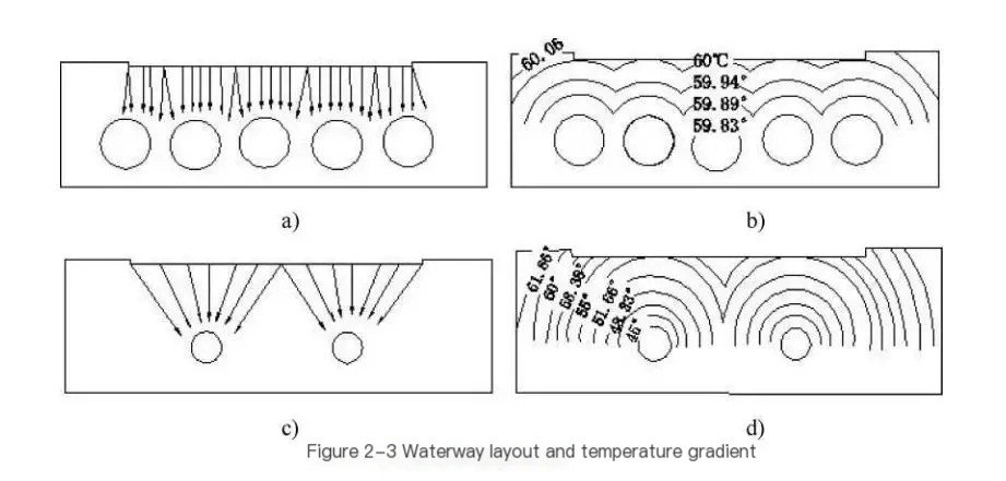
Accurately define the size and spacing of cooling water holes
Mold temperature distribution is directly tied to the size and density of water holes. As water holes get larger in diameter and more closely spaced together, temperature distribution becomes more even; typically center-to-center distances between tubes range from 3 to 5 times their diameters; Figure 2-3a) and b) provide uniform temperature distribution on the cavity surfaces whereas structures shown in Figures 2-3c) and d) produce large temperature ranges, from 45degC to 61.66degC which result in uneven shrinkage across various parts of products.
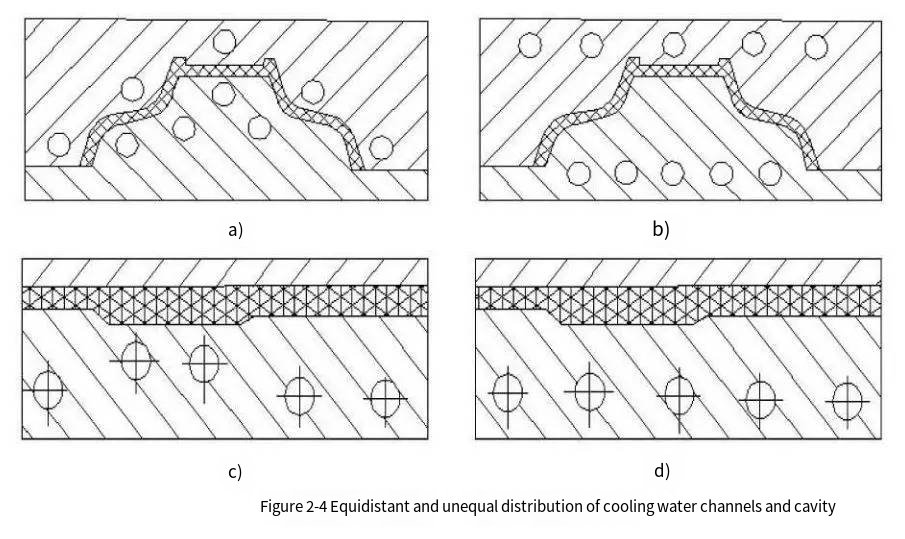
The distance between the cooling pipeline and the cavity surface should be reasonable
Too large a distance and high thermal resistance will reduce cooling efficiency, while too small a distance will cause uneven surface temperature of the cavity. According to experience, the distance between the cooling water channel and the cavity surface is between 1 and 2 times the diameter of the pipe, which is appropriate. For parts with constant thickness, the distance between the water hole and the cavity surface should be equal to ensure uniform cooling, as shown in Figure 2-4, a) is better than b). For parts with varying thickness, cooling should be strengthened at the wall thickness. As shown in Figure c) is better than b).
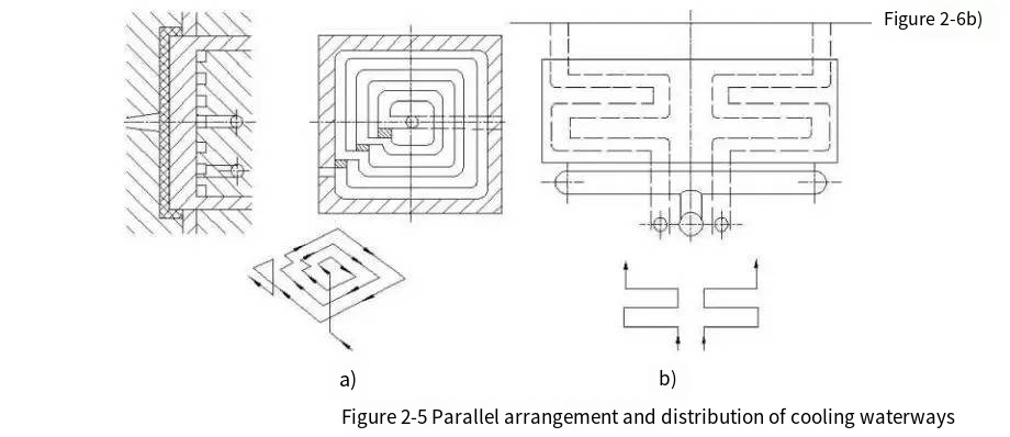
Water and material are processed in parallel to enhance the cooling at the gate
Since the melt is injected into the cavity from the gate, the temperature near the gate is the highest, and it is necessary to strengthen cooling near the gate, using this area as the inlet for cooling liquid, and making the overall flow direction of the cooling water tend to be the same as the direction of the plastic melt flow (water and material in parallel). Figure 2-5a) shows the cooling water path arrangement for a gate in the center position; Figure 2-5b) shows the cooling water path arrangement for a film gate.
Use all possible means to reduce the temperature difference between inlet and outlet water of your mold cooling pipe
Cooling liquid in molds works to absorb heat, with outlet temperatures being higher than inlets; if this difference becomes too great, its impact on surface temperature of mold cavities and cooling of plastic parts, especially larger plastic parts could become uneven. Therefore, in order to achieve approximately equal cooling speeds across products it may be advantageous to shorten cooling circuits and also minimize temperature variance between inlet and outlet water channels by strategically arranging them – something not shown here in figure 2-6a)
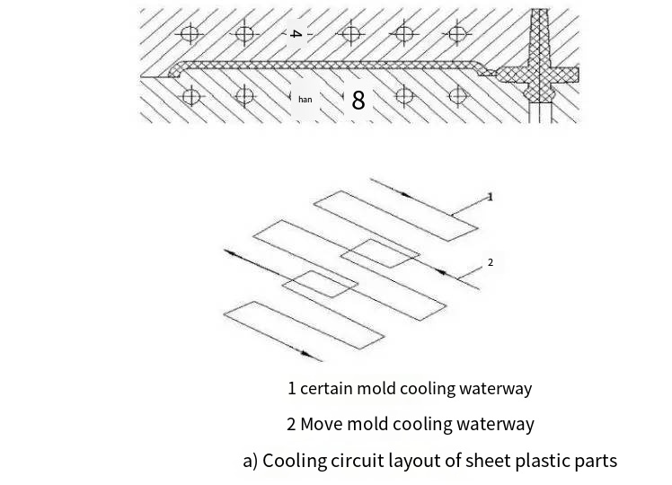
The layout of the waterway should consider the structure of the plastic parts and the properties of the plastic
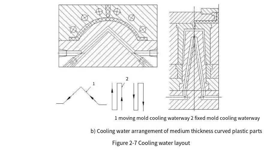
For different plastic parts, the cooling circuit should be arranged considering its size and shape specificity. As shown in Figure 2-7a, the cooling circuit layout for thin plastic parts is equally spaced between the moving and stationary mold cooling water holes and the cavity; Figure 2-7b shows the cooling water circuit layout for medium-thickness curved plastic parts, with the cavity being equally spaced between the cavity cooling water holes. The male mold is drilled with inclined holes to obtain a circuit similar to the cavity shape. Different plastics have different shrinkage rates, and the arrangement of cooling water channels will also vary.
The joint of the cooling water pipe should be designed on the same side of the mold
The cooling water channels are connected by hoses, and to facilitate connection and reduce space, it is best to design them on the same side of the mold. The water pipe joints should be lower than the outer surface of the mold, so as to prevent damage to the joints due to mold handling, which affects the sealing of the cooling water channels. At the same time, in order not to affect the operation of workers, the joints are generally located on the back of the injection molding machine. The structural design of the cooling water channel must pay attention to its processing technology, and it should be easy to process and manufacture. Simple processing techniques such as drilling should be used as much as possible. For inlaid composite cooling water channels, attention should also be paid to waterway sealing to prevent cooling water from leaking into the cavity, causing cavity corrosion.