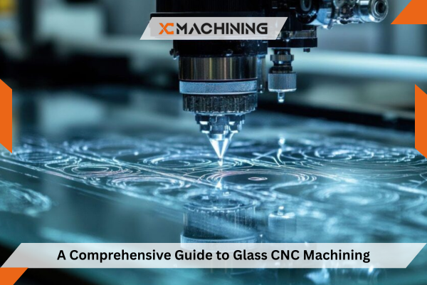
For companies that build optical devices, medical instruments, or high‑end consumer goods, the tolerance window is tight and the material is unforgiving. Glass CNC machining brings the accuracy of metalworking to brittle substrates, allowing engineers to mill, cut, and engrave glass components that once required slow handwork. By combining computer‑controlled motion with ultra‑hard diamond tools, modern shops routinely hold ±5 µm tolerances while keeping lead times short—an advantage when prototypes must become production parts quickly.
Why Glass CNC Machining Matters for Modern Industries
- Optics and photonics – microscope slides, prisms, lens blanks
- Semiconductor tooling – reticles, inspection windows
- Medical devices – lab‑on‑chip cartridges, diagnostic plates
- Clean‑tech products – flow cells for hydrogen generation
Demand for complex glass parts continues to rise as designers pursue lighter, more chemically stable components. CNC technology scales from single‑piece prototypes to thousands of units without sacrificing precision.
Machine Architecture and Processes
Glass machining centers resemble high‑speed mills but incorporate several key upgrades:
- Air‑bearing spindles to damp vibration.
- Flood the coolant with de‑ionized water to prevent staining.
- Five‑axis interpolation for complex bevels and aspheric surfaces.
Together, these features minimize subsurface micro‑cracking and preserve optical clarity.

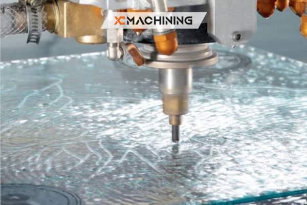
Diamond Tooling for Reliable Glass Results
Because conventional carbide wears almost instantly against silica, diamond tooling for glass CNC dominates modern production. Toolmakers either coat or braze synthetic diamonds onto routers, drills, and cup wheels, achieving tool lives three to ten times longer than ceramics.
Selecting the Right Diamonds
- Monocrystalline – best for mirror‑quality finishes under 0.05 µm Ra
- Polycrystalline – economical choice for roughing
- Chemical‑vapor‑deposited (CVD) – balanced life and cost
Recent CVD grades reduce edge chipping by nearly 20 %, extending diamond tooling for glass CNC into micro‑feature drilling.
Best Practices
- Keep spindle run‑out below 2 µm.
- Limit plunge depth to 30 µm per pass.
- Dress wheels with a silicon‑carbide stick to maintain grit exposure.
Following these steps ensures diamond tooling for glass CNC delivers predictable wear and consistent surface integrity.
Precision Glass Cutting Techniques Explained
Contemporary production blends multiple precision glass cutting techniques:
- Water‑jet scribing removes large blanks while limiting heat zones.
- Diamond sawing trims edges to within ±50 µm.
- CNC routing refines profiles to the final ±5 µm tolerance.
Using adaptive feed control, shops apply precision glass cutting techniques that adjust tool pressure in real time, reducing edge chips by up to 35 %. Optical‑grade manufacturers rely on the same precision glass cutting techniques to strengthen parts before ion‑exchange tempering.
CNC Milling Glass Materials Step by Step
CNC milling of glass materials begins at the CAM station:
- Simulation verifies toolpaths and prevents over‑cuts.
- Vacuum work‑holding secure thin sheets without stress points.
- Peck cycles evacuate debris and maintain coolant flow.
During roughing, trochoidal toolpaths lower radial forces—an approach widely adopted when CNC milling glass materials thicker than 10 mm. Finishing passes for microfluidic channels (≤ 200 µm wide) rely on micro‑diamond burrs spinning at 60000 rpm; this step closes the loop in streamlined CNC milling glass materials workflows.
CNC Engraving on Glass Surfaces Adds Value
When parts double as user interfaces, CNC engraving on glass surfaces provides legends, logos, and fiducials resistant to solvents and UV light. Laser ablation can cloud the substrate; in contrast, CNC engraving on glass surfaces with plunge‑style ball burs leaves crisp edges after a single polishing pass.
Consumer‑electronics designers now integrate light‑guide features directly by CNC engraving on glass surfaces, improving luminance uniformity by more than 10 % compared with screen‑printed diffusers.
Overcoming Machining Brittle Materials Challenges
Subsurface cracks and edge chips top the list of machining brittle materials challenges. Studies show edge chipping depends heavily on tool angle and depth, guiding engineers toward optimum feed rates.
Preventive Measures
- Toolpath optimization – continuous arcs lessen acceleration spikes, reducing many machining passes of brittle materials.
- Ion‑exchange strengthening – converting Na⁺ to K⁺ ions after machining offsets residual stress left by the typical machining of brittle materials challenges.
- Fractography – inspecting fracture mirrors helps diagnose latent cracks linked to persistent machining of brittle materials.
Adopting these methods can cut scrap rates related to machining brittle materials challenges by up to 40 %.
Quality Control and Testing for High‑Value Optical Parts
Metrology stations integrate white‑light interferometers for flatness and vision CMMs for dimensional checks. To verify strength, four‑point bend tests in line with ASTM C158 confirm crack‑free surfaces on load‑bearing windows.
Surface Finishing and Post‑Processing Options
After cutting, several techniques bring the glass to its final optical grade:
- Ultrasonic polishing uses abrasive slurry and high‑frequency vibration to achieve < 0.02 µm Ra without altering geometry.
- Fire polishing briefly melts the surface, sealing micro‑cracks left by earlier precision glass cutting techniques.
- AR or hydrophobic coatings reduce reflection and repel fingerprints; CNC engraved areas are masked to keep legends crisp.
- Edge beveling on a diamond wheel removes sharp corners that can crack during assembly.
Choosing the right post‑process depends on clarity requirements, part geometry, and downstream bonding methods.
Design Guidelines for Engineers
Smart design lowers cost and improves yield:
- Avoid 90° inside corners—a 0.5 mm fillet cuts stress points, easing many machining brittle materials challenges.
- Respect minimum wall thickness—keep it above two tool diameters when CNC milling glass materials to prevent breakout.
- Plan fixture access—add flat pads so vacuum tables can grip securely during CNC engraving on glass surfaces.
- Specify finish zones—call out optical‑grade areas separately; rougher sealed edges cost less to the machine.
Early collaboration with the shop transforms drawings into parts that flow smoothly through the entire glass CNC machining sequence.
Cost Factors and Lead Times
| Cost Driver | Typical Range | Impact on Final Price |
| Diamond tool wear | 5 %–15 % | Frequent tool change adds overhead |
| Machine capital | USD 450k–900k | Amortized across large volumes |
| Material grade | USD 3–12 / kg | Fused silica costs three times soda‑lime |
| QA protocols | 8 %–12 % | Mandatory for medical and aerospace |
Local suppliers often offset higher labor rates through shorter transit times, trimming project lead time by several weeks compared with distant imports.
Conclusion
Glass CNC machining transforms brittle substrates into mission‑critical components for optics, medical devices, and clean‑tech. By mastering diamond tooling, adaptive cutting paths, and rigorous QA, manufacturers can deliver defect‑free parts on time and on budget, helping XC Machining stand out in today’s competitive precision‑manufacturing landscape.
FAQs
How small can a hole be drilled in glass via CNC?
Specialty diamond drills achieve 0.3 mm diameter, provided the coolant flow is maintained.
What surface finish can CNC achieve on optical glass?
With monocrystalline diamond tools, a roughness of 0.02 µm Ra is achievable before polishing.
Is CNC safer than manual glass grinding?
Enclosed guards and closed‑loop coolant systems reduce operator exposure to shards and silica dust.


