
Are you struggling to get your parts just right when they come off the machine? Maybe your corners aren’t as crisp as you expected, or you’re battling awkward tool paths that slow everything down. It can be frustrating to invest time in a design only to realize later that it’s not friendly for 3-Axis CNC Machining. Don’t worry, my friend—you’re not alone in this.
In this guide, we’ll break down practical tips—like tool access planning and corner radii—and show you how to streamline your design for maximum efficiency. By the end, you’ll be ready to create parts that machine faster, cost less, and work exactly as you intend.
A Quick Overview of 3-Axis CNC Machining
Before diving into design specifics, let’s clarify what the three-axis means. In 3 axis CNC machining, the CNC cutting tool moves along the X, Y, and Z axes. Parts can be shaped from various angles within those three coordinates, making it great for a broad range of simpler yet robust component designs.
Understanding Linear Movements
In three-axis setups, motion is linear, not rotational. The spindle moves along each axis independently. This means milling surfaces is simple, though you can’t tilt or rotate the workpiece. Designing for these linear movements prevents collisions and ensures tool paths.
Setting Up The Workpiece
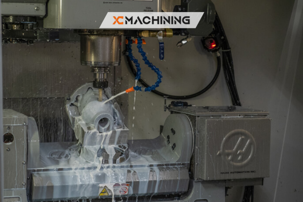
Clamping and fixture design matter. A secure, stable piece prevents vibration and tool deflection. Most 3-axis machines position the stock so all operations happen from one direction. Planning your setup around this constraint reduces errors and helps maintain part geometry.
Tooling Considerations
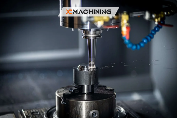
Cutter diameter, flute length, and feed rate impact surface finish. In 3-axis CNC Machining systems, shorter tools minimize chatter and boost accuracy. Plan enough clearance for the spindle. Picking the right end mill profile also helps manage material removal and finish quality.
Designing With Tool Access In Mind
Tool accessibility is a key concern in CNC machining. Because the cutter can only approach from vertical and horizontal angles, it’s crucial to avoid shapes that block the tool path. Overlooking this can lead to unreachable pockets or partly machined surfaces.
For better tool access, consider the following:
- Use open pockets rather than deep, enclosed pockets.
- Maintain generous corner radii so tools can fit without over-stressing.
- Simplify geometry to avoid multiple setups or complex fixture changes.
Additionally, think about the maximum reach of your tooling in 3-Axis CNC Machining. Longer tools introduce vibration and can compromise accuracy. If an area requires an excessively long cutter, reevaluate the shape or break the design into sub-components. Balancing these factors helps you streamline 3-Axis CNC Machining production and reduce the risk of tool damage.
Always confirm your design lines up with the standard tool lengths available in your shop. This alignment lowers setup times since machinists won’t need special or custom tooling. Fewer specialized tools translate into faster runs and less potential for machining errors.
Leveraging CAD/CAM Software For Optimal Paths
Today’s CAD/CAM programs offer simulation tools that help you plan each cut in 3 axis CNC machining. By running a virtual mock-up, you can spot collisions, uncut areas, or inefficient travel paths before a single chip is made.
Advanced software modules generate toolpaths tailored to your geometry, optimizing 3-Axis CNC Machining by reducing air cuts and redundant passes. They also allow for smoother transitions between roughing, semi-finishing, and finishing operations, enhancing 3-Axis CNC Machining efficiency. This synergy leads to better surface finishes and often requires fewer manual interventions on the shop floor.
Remember to keep your design’s geometry as clean as possible in the digital model. Gaps, overlapping surfaces, or unnecessary features can confuse the toolpath generator in 3-Axis CNC Machining, causing erratic or suboptimal results. A tidy, well-structured model ensures seamless translation from the screen to the spindle.
Minimizing Overhangs And Undercuts
3 axis CNC machining only gives you movement along three axes, which means certain features can be tough to produce. Overhangs and undercuts fall into this challenging category. If your design includes these elements, you risk partial inaccessibility that may require manual finishing or extra setups.
For a design that’s kinder to your machinist, keep these in mind:
- Reduce undercut depth when possible.
- Incorporate draft angles for an easier tool approach.
- Explore alternate assembly methods if critical overhangs are unavoidable.
Parts with complex recesses might be better suited for multi-axis machining or might need specialized cutters. However, if you must stick to the three-axis, refining the geometry to eliminate hidden zones ensures a smoother workflow. This not only saves time but also cuts production costs.
Sometimes, it’s impossible to remove every overhang. In these cases, consult your manufacturing partner to decide whether custom fixtures or angled setups can solve the problem. Collaborative planning can reveal innovative ways to achieve your goals without sacrificing crucial design features.
Choosing The Right Materials
Not all materials behave the same under 3-Axis CNC Machining. Metals like aluminum cut easily and handle higher speeds, while harder steels need more conservative feeds to prevent tool wear. Plastics can melt or warp if the spindle runs too hot or too fast, affecting 3-Axis CNC Machining precision.
When designing for 3-Axis CNC Machining, consider the thermal and mechanical properties of your chosen material. Thinner sections in certain plastics might flex or vibrate, causing inaccuracies. For metals, keep in mind that different alloys will respond differently to cutting forces. Matching material properties to your design constraints prevents frustration later on.
Always consult material datasheets or talk with suppliers to ensure you pick a substance that aligns with your performance requirements and machining capacity. Striking a balance between hardness, machinability, and cost is key to a successful final product.
Streamlining Hole And Feature Placement
Hole locations, slot placements, and cutouts are integral to many parts. However, in 3 axis CNC machining, the tool approaches from above or the side, so angles or positions that block a straight path can become problematic.
Consider these pointers:
- Align holes with standard drill sizes.
- Space holes apart so the tool can fully retract.
- Avoid angled features that require tilt or specialized jigs.
Keeping holes on flat, easily accessible surfaces reduces cycle time and the likelihood of errors. For example, placing a hole too close to a wall can limit the tool’s ability to move freely, causing collision risks. Plan your geometry to minimize these potential headaches.
Likewise, standardizing hole diameters simplifies tool changes. Fewer size variations let the operator use a single drill or end mill, reducing run times. That translates directly into lower costs and faster delivery for your projects.
Using Standard Tool Sizes And A Table For Reference
In 3 axis CNC machining, standardizing tool sizes can drastically cut down on complexity. By choosing cutters that shops already stock, you reduce lead times and potential mistakes. Let’s look at some typical end mill sizes and their common uses in the table below.
| Tool Diameter (mm) | Recommended Pass Depth (mm) | Common Use |
|---|---|---|
| 3 | 1–2 | Fine detail, small slots |
| 6 | 2–4 | General milling tasks |
| 10 | 3–5 | Rapid material removal |
This table gives a rough guideline. Each shop may have its own preferred parameters based on machine horsepower and tooling inventory. Ensuring your design aligns with these standards helps avoid bottlenecks when it’s time to machine your part using 3-Axis CNC Machining.
Also, remember that shorter tools can run faster and with less chatter. If your design mandates a deep pocket, verify that an extended reach tool is truly necessary. Overly long tools can slow production and increase the risk of cutter breakage.
Factoring In Tolerances And Fits
Precision is a hallmark of 3 axis CNC machining, but you still need to set realistic tolerances. Overly tight specs can drive up costs and increase the number of required inspections. Loose tolerances, on the other hand, might compromise the functionality of your assembly.
To strike the right balance:
- Define tolerances crucial only to function.
- Remember that each added decimal increases machining time.
- Communicate specific fits (like press or slip) to your manufacturer.
Even the 3-Axis CNC Machining machine’s thermal expansion or tool wear can introduce minor variations. By specifying only the tight tolerances you truly need, you enable faster production and reduce scrap. Collaboration with your machinist ensures your part’s geometry remains both functional and cost-effective.
A thorough review of your design can pinpoint non-critical areas where standard tolerances suffice. This approach keeps everything simpler for both the CAD/CAM process and the final runs, saving you headaches and budget in the long haul.
Reducing Setup Time Through Clever Design
Multiple setups slow production and introduce error risks. In 3 axis CNC machining, each re-clamping changes the part’s orientation, which can misalign features if not done carefully. By designing parts with a single orientation in mind, you can streamline the process significantly.
Keep as many features as possible accessible from one vantage point. For instance, place holes, pockets, or engraved text on the top face if you can. Minimizing rotations or flipping leads to faster turnaround and fewer fixture complications.
If your part absolutely requires multiple orientations, plan flat surfaces for easy referencing. This approach gives the operator a consistent alignment point each time. With thoughtful design, you’ll cut down on your shop’s setup transitions and enjoy more reliable results.
Accounting For Tool Deflection And Chatter
When a cutter makes contact with material in 3 axis CNC machining, forces can cause slight deflection. This deflection leads to inaccuracies, especially in slender tools or extended lengths. Chatter, the vibration between the tool and material, can mar your surface and shorten tool life.
To handle these issues effectively:
- Keep tool length as short as possible.
- Choose rigid tooling and holders.
- Adjust feed rates to balance speed and stability.
Observing these guidelines in 3-Axis CNC Machining helps maintain dimensional accuracy. Too much deflection might show up as tapered walls or uneven depths. You might also see tool marks that require post-processing to remove. By cutting chatter and deflection, you’ll produce cleaner parts right off the machine.
Understanding how different materials respond to force is crucial in 3-Axis CNC Machining. Softer metals might be more prone to chatter if you push speeds too high, while harder alloys demand a careful approach to avoid snapping the cutter. Fine-tuning these parameters keeps your project on track.
Adding Corner Radii In Internal Pockets
Internal corners pose a challenge in 3 axis CNC machining because tools are round. If you design a perfectly sharp inside corner, the cutter can’t reach that 90-degree angle. Instead, you’ll end up with a radius that may interfere with parts meant to fit there.
To avoid big reworks, incorporate a fillet radius that matches or slightly exceeds your tool’s diameter. This step not only ensures the tool can complete the cut but also reduces stress concentrations in the final product.
For precision assemblies, double-check that your mating parts account for this radius. If a perfectly square corner is essential, you may need supplementary operations, such as 3-Axis CNC Machining, EDM (Electrical Discharge Machining), or hand finishing. However, for most designs, a well-planned radius is more efficient.
Applying Efficient Roughing And Finishing Operations
In 3 axis CNC machining, roughing quickly removes the bulk of material, while finishing refines details. A well-planned roughing strategy uses larger tools to hog out as much stock as possible. Afterward, smaller end mills handle precise finishing passes.
Designing with these steps in mind can influence how you dimension pockets and walls. For instance, leaving a consistent “allowance” for finishing ensures a uniform final pass. This approach gives you smoother walls and a consistent surface.
Additionally, some CAM software offers specialized toolpath strategies like trochoidal or adaptive clearing. These methods maintain constant cutter engagement and can prolong tool life. By dividing your design into logical sections for roughing and finishing, you boost efficiency and part quality.
Planning For Post-Processing And Finishes
Even the best-machined part might need post-processing. Whether it’s 3-Axis CNC Machining for precision components or finishing touches like anodizing on aluminum, a coat of paint, or a mirror polish on steel, these processes can slightly alter dimensions or require additional surface prep.
If your design includes tight tolerances, factor in finishing thickness. Coatings and plating add material that could affect assembly. Often, a slight oversize in critical areas can compensate for the finishing layer. Consulting your finishing provider early helps avoid surprises in 3-Axis CNC Machining projects.
Also, consider how post-processing impacts edges or corners. Anodizing, for example, can round off sharp edges or fill small details. By anticipating these effects from the start, you’ll reduce the risk of losing essential features or affecting your part’s appearance.
Embracing Collaboration Early
Designing in isolation can lead to rework. By involving machinists and production teams at the concept stage, you get real-world input on feasibility. They’ll quickly spot if a feature is too intricate or if a certain radius is unrealistic.
This collaborative approach can also uncover alternative design paths that maintain function while simplifying machining. A small tweak in the corner radius or a slight shift in hole placement might save hours of production time.
Early feedback reduces design churn and shortens your overall product development cycle. Plus, it builds a smoother relationship with your manufacturing partner. Communication is key to achieving a design that meets both aesthetic and technical requirements in a single shot.
Conclusion
In summary, optimizing your designs for 3 axis CNC machining involves balancing geometry, tooling, and material choice. By carefully planning each feature—from corner radii to hole placement—you can create parts that are both easy to machine and functionally robust.
Remember to keep tool access open, limit unnecessary complexity, and pick materials that fit your machining strategy. Collaborating with experts early in the design process will save you time and resources while also delivering consistent and high-quality results.
FAQs
What is the most common mistake in 3-axis design?
One frequent error in 3-Axis CNC Machining is forgetting to include corner radii in internal pockets. Sharp inside corners aren’t possible with round tools, leading to unnecessary rework.
How do I minimize vibration when using longer tools?
Reduce spindle speeds, use a shorter flute length if possible, and choose rigid tool holders. Sometimes, using specialized cutters designed for deep reaches also helps.
Should I always aim for the tightest tolerance?
Not necessarily. Tighter tolerances increase machining time and cost.Use close tolerances only where needed for function, and loosen them in non-critical areas.


