Skip to content
Introduction
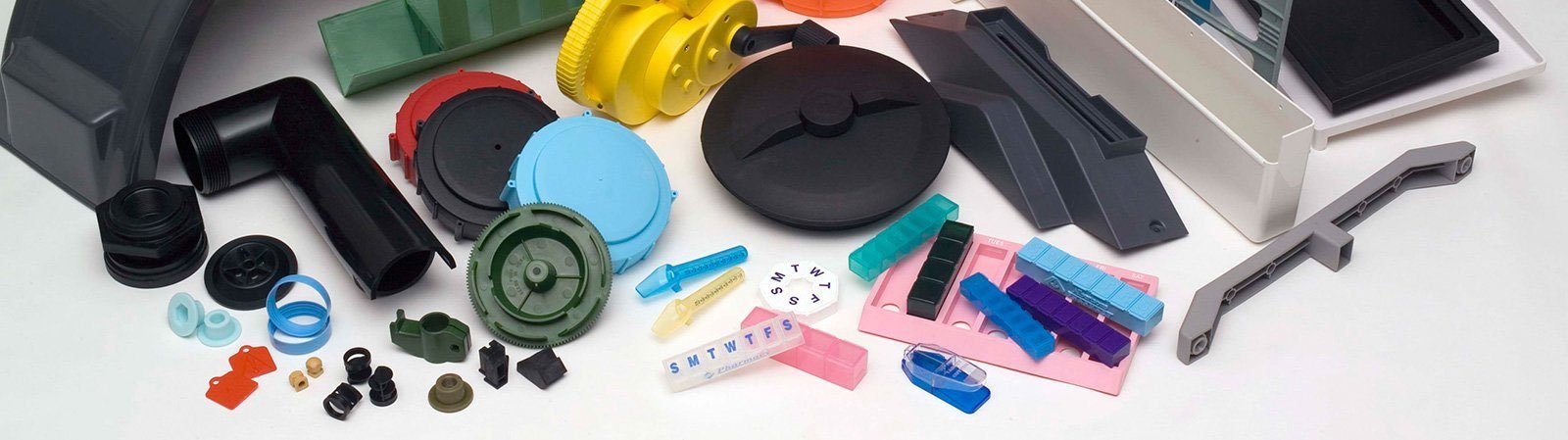
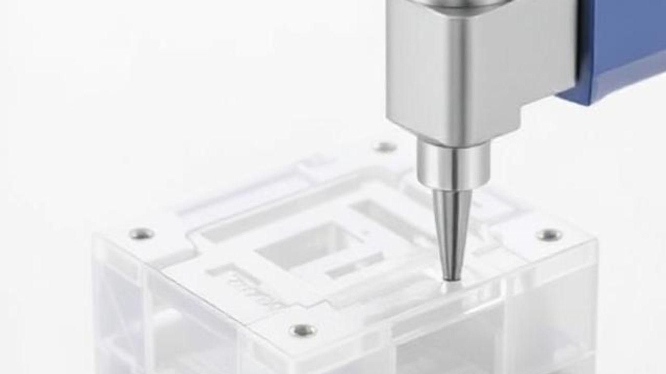
Injection Molding
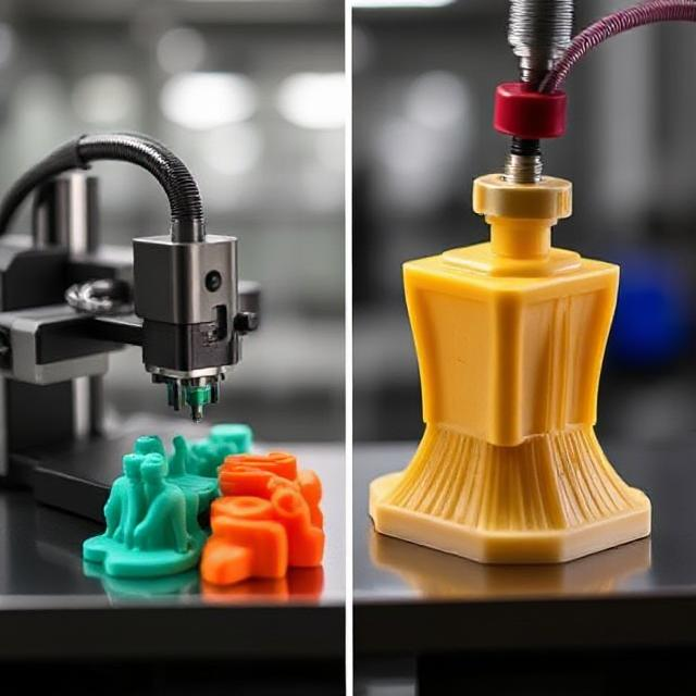
Injection molding is an efficient means of producing plastic products; it also ensures they have full structure and accurate dimensions. Used widely in mass production of complex shaped parts, injection molding involves injecting heated and molten plastic under high pressure into mold cavities before cooling and solidifying to form the final molded product.
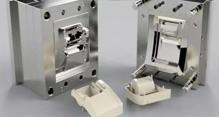
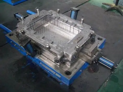
Mold Composition
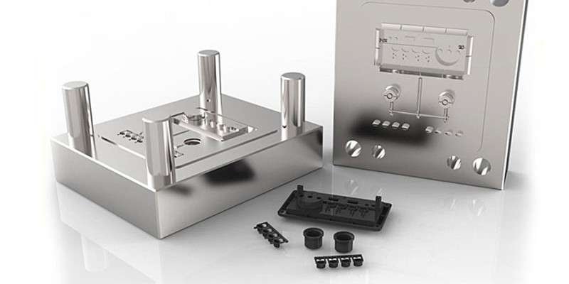
Although mold structures vary depending on factors like plastic types and properties, shape of plastic product, injection machine type and more, their basic framework remains constant. A mold typically includes casting system components like casting system parts that directly interact with plastic product and temperature control systems as well as mold parts that come in direct contact with it as well as structural parts – these latter two being particularly complex parts that must operate precisely. Mold components consist of casting system, temperature control system components such as temperature probes as well as molding components which directly touch plastic surface for manufacturing purposes – with casting system components playing direct role relating to plastic product/plastic product interaction as they play such an integral part of mold composition that requires great smoothness and accuracy from within this form of apparatus.
Injection molds consist of two components – a moving mold and stationary mold – connected by hinges. During injection molding, these two molds come together to form the gating system and cavity for plastic products to enter; once opened they can be separated for easier removal. Standard mold frames can reduce workload considerably for designing and manufacturing injection molds.
Exhaust port
It is a groove-shaped vent opened in the mold to discharge the gases originally present and brought in by the melt. When the melt is injected into the cavity, the air originally present in the cavity and the gases brought in by the melt must be discharged outside the mold through the vent at the end of the material flow, otherwise it will cause the product to have pores, poor bonding, incomplete filling, and even burn the product due to high temperature caused by compressed accumulated air. Generally, the vent can be located either at the end of the melt flow in the cavity or on the parting surface of the mold. The latter is a shallow groove with a depth of 0.03-0.2mm and a width of 1.5-6mm on one side of the female mold.
During injection, there will not be much melt leakage from the vent hole because the melt will cool and solidify there, blocking the channel. The vent hole should not be located directly in front of the operator to prevent accidental melt ejection and injury. In addition, the clearance between the ejection rod and the ejection hole, as well as the clearance between the ejector block and the core, can be used to vent air.
The function of the exhaust slot
The main functions of the vent slot are two-fold: first, it removes air from the mold cavity during injection of molten material; second, it removes various gases generated during the heating process of the material. The thinner the product and the further away from the gate, the more important it is to have a vent slot.
In addition, for small or precision parts, it is also important to pay attention to the opening of the exhaust slot, as it can not only avoid surface burns and insufficient injection volume of the product, but also eliminate various defects of the product and reduce mold contamination.
So, how can we determine whether the venting of the mold cavity is sufficient? Generally speaking, if the molten material is injected at the highest injection rate and no scorch marks are left on the product, it can be considered that the venting of the mold cavity is sufficient.
Exhaust mode
There are many methods for venting the mold cavity, but each method must ensure that the venting groove can prevent material from overflowing into the groove while venting, and also prevent clogging. Therefore, measuring from the inner surface of the mold cavity to the outer edge of the mold cavity, the height of the venting groove with a length of 6-12mm or more should be increased by about 0.25-0.4mm. In addition, too many venting grooves are harmful. Because if the clamping pressure acting on the part of the mold cavity without a venting groove is too high, it can easily cause cold flow or cracking of the mold cavity material, which is very dangerous.
In addition to venting the mold cavity on the parting surface, it is also possible to achieve the purpose of venting by setting an exhaust slot at the end of the material flow of the gating system and leaving a gap around the ejection rod. The depth, width, and location of the exhaust slot are not appropriate, resulting in burrs that affect the appearance and accuracy of the product. Therefore, the size of the gap is limited to prevent burrs around the ejection rod.
It should be noted that when exhausting gears, even the smallest fliers are not desirable. The following methods are recommended for this type of part:
(1) Thoroughly remove the gas in the flow channel;
(2) The mating surface of the parting surface is treated with a 200# silicon carbide abrasive by shot blasting. In addition, an exhaust slot is provided at the end of the pouring system flow, mainly at the end of the splitter channel. The width of the exhaust slot should be equal to the width of the splitter channel, and the height varies depending on the material.
Design method
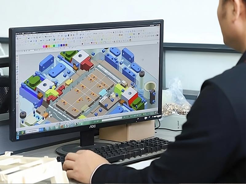
Based on years of experience in injection mold design and product testing, this article briefly introduces the design of several vent slots.
For complex geometric shapes of product molds, the opening of the exhaust slot is best determined after several trial molds. The biggest disadvantage of the overall structural form in mold design is poor exhaust.
There are several exhaust methods for the overall cavity mold core:
(1) Use the groove or insert installation area of the cavity;
(2) Utilize the side insert seam;
(3) partial helical shape;
(4) Install a grooved Flat noodles center and open a process hole on the longitudinal position;
When it is difficult to exhaust, adopt the inlay structure, etc. If it is not easy to open the exhaust slot in some molds with dead ends, firstly, without affecting the appearance and accuracy of the product, appropriately change the mold to an inlay process. This is not only beneficial for processing the exhaust slot, but sometimes it can also improve the original processing difficulty and facilitate maintenance.
Design of exhaust slot during thermosetting plastic molding
The exhaust heat of thermosetting materials is more important than that of thermoplastic materials. Firstly, the runner ahead of the gate should be exhausted. The exhaust slot width should be equal to the runner width, and the height should be 0.12mm. The exhaust slots should be placed around the mold cavity, with a distance of 25mm between each slot, a width of 6.5mm, and a height of 0.075-0.16mm, depending on the fluidity of the material. The lower value should be taken for softer materials. The ejection rod should be enlarged as much as possible, and on most occasions, the cylindrical surface of the ejection rod should be ground with 3-4 planes with a height of 0.05mm, with the grinding direction along the length direction of the ejection rod. The grinding should be carried out with a fine-grained grinding wheel. The end face of the ejection rod should be ground with a chamfer of 0.12mm, so that if any flash is formed, it will adhere to the part.
Conclusion
Properly opening exhaust slots can greatly reduce injection pressure, injection time, holding time, and clamping pressure, making plastic molding easier and improving production efficiency, reducing production costs, and reducing energy consumption of the machine.