FDM 3D Printing Services
XC Machining FDM 3D printing extrudes thermoplastic filament through a heated nozzle layer-by-layer at 100–300 μm resolution — producing large parts up to 914 × 610 × 914 mm in PLA, ABS, PETG, ASA, Nylon PA12, PC, TPU, PEEK, and ULTEM (PEI). Standard tolerance: ±0.2 mm (desktop) / ±0.13 mm (industrial FDM). Lowest cost per cubic centimeter of any 3D printing process. Parts in 1–5 business days from Dongguan, China.
- All uploads are secure and confidential
What Is FDM 3D Printing at XC Machining?
FDM (Fused Deposition Modeling) 3D printing extrudes molten thermoplastic filament through a 0.4 mm nozzle along CNC-programmed toolpaths, depositing layers at 100–300 μm thickness that cool and bond into a solid part. FDM supports the widest material range of any polymer 3D printing process — from PLA to PEEK and ULTEM — at the lowest cost per part.
FDM 3D Printing Solutions for High-Performance Parts
When you need reliable and durable parts, XC Machining offers the best FDM 3D printing services in the USA. Our Fused Deposition Modeling 3D printing services allow for quick production of high-performance, custom parts using a wide range of materials.
Tolerances for Fused Deposition Modeling (FDM)
At XC Machining, we offer Fused Deposition Modeling (FDM) 3D printing services that are perfect for rapid prototyping and functional parts production.
| Description | Specification |
| General Tolerances | Metals: ISO 2768-m |
| Plastics: ISO 2768-c | |
| Precision Tolerances | Tolerances as tight as ±0.2 mm, per drawing specs and GD&T annotations |
| Minimum Wall Thickness | 0.8mm |
| Minimum Layer Thickness | 0.1mm |
| Minimum Part Size | 20mm x 20mm x 1mm |
| Maximum Part Size | 300mm x 300mm x 400mm |
| Production Volume | Prototyping: 1-100 pcs |
| Low Volume: 101-5,000 pcs | |
| High Volume: Above 5,000 pcs | |
| Lead Time | 3-5 business days for most projects. Simple parts can be delivered as fast as 1-2 days |
Why Choose XC Machining for FDM 3D Printing Services?
XC Machining FDM 3D printing offers the largest build volume (914 × 610 × 914 mm), widest material range (PLA to ULTEM), and lowest cost per cubic centimeter of any polymer 3D printing process. ±0.2 mm standard tolerance, 100–300 μm layers, DFM review within 12 hours, parts in 1–5 business days from Dongguan, China.

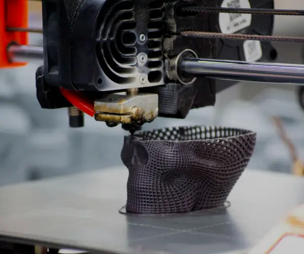
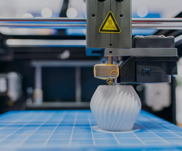
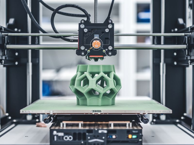
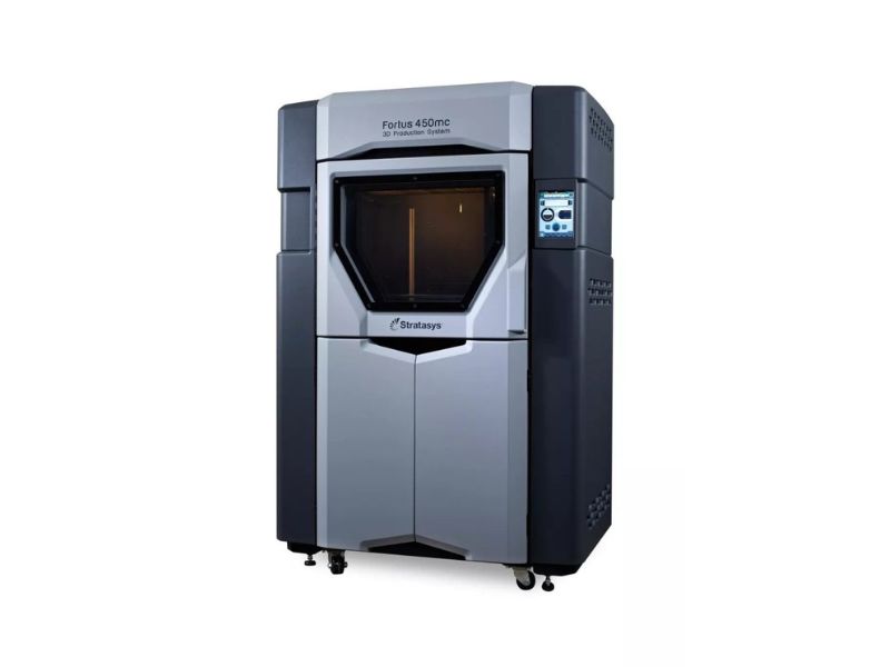
XC Machining industrial FDM prints parts up to 914 × 610 × 914 mm in a single build — larger than any SLA, SLS, or MJF build volume. This makes FDM the only practical 3D printing method for automotive body panel prototypes, architectural models at 1:1 scale, large industrial enclosures, and furniture or consumer appliance mockups. Parts too large for a single build are printed in sections and bonded with structural adhesive to produce seamless assemblies.

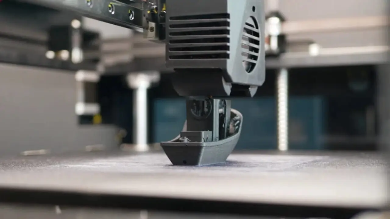
FDM uses the least expensive consumable of any polymer 3D printing process — thermoplastic filament at $15–$80/kg versus SLA resin at $100–$400/L or SLS powder at $80–$200/kg. Combined with no tooling cost, 15–20% infill (hollow interior), and fast print speeds, FDM produces concept models and functional prototypes at 50–70% lower cost than SLA or SLS for equivalent part volumes above 50 cm³.

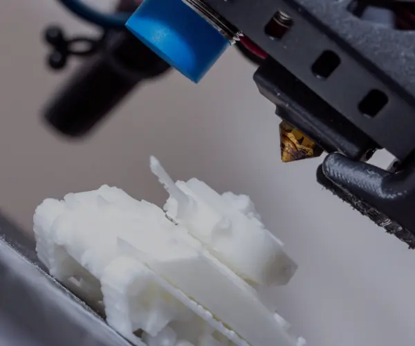
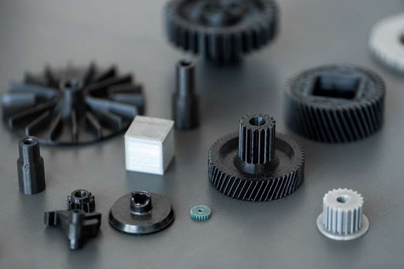
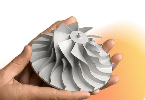
Machining FDM covers the full thermoplastic range: PLA (60 MPa, concept models) → PETG (50 MPa, food-contact) → ABS (40 MPa, functional) → Nylon PA12 (85 MPa, tough) → PC (65 MPa, impact) → PEEK (100 MPa, chemical and thermal) → ULTEM PEI (73 MPa, aerospace FST-rated, sterilizable). Material recommendation is provided during DFM review based on temperature, chemical, mechanical, and regulatory requirements.

Upload STL or STEP file. XC Machining engineers return DFM review within 12 hours: anisotropy analysis (primary load axis orientation), wall thickness check, overhang and support strategy, infill recommendation, material selection, and shrinkage compensation on critical fits. Every FDM DFM review includes a specific build orientation recommendation to maximize Z-axis strength for the part's primary loading condition.
What Surface Finishes Are Available for FDM 3D Printed Parts?
XC Machining FDM surface finishes: as-printed (Ra 6–16 μm, visible layer lines), sanded (Ra 1.6–3.2 μm, 120–400 grit), primed and painted (Ra 0.4–1.6 μm, RAL/Pantone matched), acetone vapor smoothed (ABS only, Ra 0.5–2 μm, semi-gloss sealed), and epoxy coating (Ra 0.1–0.4 μm, high-gloss, structural reinforcement).
FDM parts emerge from the printer with visible layer lines — a staircase effect from 100–300 μm layer height. Surface roughness: Ra 6–16 μm. Downward-facing surfaces (support contact) are rougher: Ra 8–20 μm. Acceptable for functional prototypes, jigs, fixtures, internal components, and parts where dimensional function matters more than aesthetics. Layer lines run perpendicular to the build direction, making them most visible on curved surfaces.
Manual sanding (120 → 220 → 400 grit, wet or dry) reduces layer lines and support witness marks. Surface roughness after 400-grit sanding: Ra 1.6–3.2 μm. Sanding reduces part dimensions by 0.05–0.2 mm per sanded surface — XC Machining compensates on critical features by scaling up before printing. Used as preparation for priming and painting, or as standalone finish for mechanical mating surfaces where Ra 1.6–3.2 μm is acceptable.
Two-coat spray painting: automotive-grade primer (40–60 μm) + polyurethane topcoat (40–80 μm). Surface roughness: Ra 0.4–1.6 μm. RAL and Pantone color matching. Matte, satin, and gloss finishes (gloss: 85+ GU at 60°). UV-resistant clear coat for outdoor or display FDM parts. Total film thickness: 80–140 μm — accounts for ±0.04–0.07 mm on critical dimensions.
ABS FDM parts are exposed to acetone vapor in a sealed chamber, which slightly melts and re-flows the outermost surface layer. Surface roughness: Ra 0.5–2 μm (from Ra 6–16 μm as-printed). Produces a semi-gloss, sealed surface that eliminates layer lines and reduces porosity. Only available for ABS material — acetone does not affect PLA, PETG, or engineering-grade materials. Reduces part dimensions by 0.05–0.15 mm uniformly.
Two-component epoxy resin applied by brush or spray to FDM part surfaces. Fills layer lines and produces a high-gloss, hard shell. Surface roughness: Ra 0.1–0.4 μm after light sanding of cured epoxy. Film thickness: 0.5–2.0 mm per coat — increases part dimensions and adds structural reinforcement (20–40% increase in surface hardness). Used for display models, master patterns for investment casting, and outdoor parts requiring UV and moisture resistance.
XC Machining applies functional coatings to FDM parts: conductive coating (copper or nickel plating on ABS, Ra 1.6 μm, surface resistance < 1 Ω/sq) for EMI shielding prototypes; anti-static coating for ESD-sensitive component handling jigs; and heat-resistant ceramic coating (service temperature to 250°C) for PEEK and ULTEM parts used in elevated-temperature applications. Coating thickness: 5–50 μm depending on type.
Materials for Fused Deposition Modeling (FDM) Parts
Black, Blue, Dark Grey, Ivory, Red, White.
6061, 7075, Black (electrostatic dissipative properties)
Translucent Natural, Translucent Amber, Translucent Red
Black, Dark Blue, Dark Gray, Light Gray, Green, Ivory, Orange, Red, White, Yellow
Black
Black
White
Translucent Natural, White
Black, Blue, Red, White
Black, Tan
Amber (Natural)
Our Fused Deposition Modeling (FDM) Prototype Manufacturing Capabilities
Provides injection molding for prototypes and custom parts, emphasizing expert support, competitive pricing, and faster production cycles.
Get reliable vacuum casting services for high-quality prototypes and production parts at competitive prices. XinCheng offers highly detailed casting parts with consistent quality.
Uses cutting, bending, and forming techniques to produce precision metal components suited for industrial, commercial, and manufacturing applications.
Specialist Industries
Bring Your Designs to Life with XC Machining
- Expertise Shared Widely
- Market Reach Expanded
- Advanced Technology Integrated
- Collaborative Innovation Opportunities
- All uploads are secure and confidential
Fused Deposition Modeling (FDM) FAQs
What Tolerance Does XC Machining Hold for FDM 3D Printed Parts?
Desktop FDM standard tolerance: ±0.2–0.5 mm (material and machine dependent). Industrial FDM (Stratasys Fortus-class) tolerance: ±0.13 mm standard. Z-axis tolerance is typically 20–30% looser than XY due to layer height step effect. Material shrinkage during cooling — PLA: 0.3%, ABS: 0.8%, Nylon: 1.5–2.0% — is compensated by pre-scaling in slicing software. For critical assemblies, XC Machining recommends printing a test coupon and measuring actual shrinkage before the production run.
What Is Anisotropy in FDM 3D Printing and Why Does It Matter?
FDM parts are anisotropic — tensile strength varies by direction. XY-plane strength (along extrusion paths): ABS 40 MPa, PLA 60 MPa, Nylon 50–85 MPa. Z-axis strength (build direction): 50–75% of XY due to interlayer bonding limits. This means FDM parts loaded perpendicular to the build direction (Z-axis) are significantly weaker. XC Machining engineers orient every part during DFM review so the primary load axis aligns with the XY plane — maximizing functional strength.
What Materials Are Available for FDM 3D Printing at XC Machining?
XC Machining FDM supports: PLA (60 MPa, concept models), ABS (40 MPa, functional housings, acetone smoothable), PETG (50 MPa, chemical resistant, food-contact safe), ASA (45 MPa, UV stable outdoor), Nylon PA12 (50–85 MPa, tough, fatigue resistant), PC (65 MPa, high impact), TPU (flexible, Shore A 85–95, 300–600% elongation), PEEK (100 MPa, 250°C service, chemical resistant), and ULTEM PEI (73 MPa, 217°C HDT, aerospace FST-rated, sterilizable).
What Is the Maximum Part Size XC Machining Can FDM 3D Print?
XC Machining’s industrial FDM build volume: 914 × 610 × 914 mm — the largest of any polymer 3D printing process. Parts larger than this are printed in sections and bonded with structural adhesive and mechanical fasteners to produce seamless assemblies. No other 3D printing process — SLS, SLA, or MJF — approaches FDM’s maximum build volume for large-format prototypes.
What Is the Lead Time for FDM 3D Printed Parts at XC Machining?
Lead time: 1–3 business days for small to medium FDM parts (< 300 mm in any dimension, standard materials PLA/PETG/ABS). 3–5 business days for large-format parts (> 300 mm) or engineering-grade materials (Nylon, PC, PEEK, ULTEM requiring heated chamber builds). Rush delivery: 24 hours for small simple parts in PLA or PETG. DFM review and quote returned within 12 hours of STL or STEP file upload.
When Should I Choose FDM Instead of SLS or SLA for My 3D Printed Part?
Choose FDM when: (1) part size exceeds 340 mm in any dimension — only industrial FDM reaches 914 mm; (2) material must be PEEK or ULTEM — not available in SLS, SLA, or MJF; (3) cost is the primary driver — FDM is 50–70% cheaper per cm³ than SLA or SLS on large solid parts; (4) jigs, fixtures, or manufacturing tooling is needed at 1-day turnaround; (5) overnight iteration is required — FDM is the fastest from file to part on simple geometries.
What Is Infill Density and How Does It Affect FDM Part Strength?
Infill density sets the percentage of solid material inside an FDM part between the outer walls. 15–20% infill: lightweight, 30–40% of solid part strength — for concept models. 50–60%: balanced weight and function. 80–100%: near-solid, maximum strength for structural parts and tooling. Infill pattern (gyroid, honeycomb, grid) affects strength-to-weight ratio — gyroid provides the highest isotropic infill strength at a given density. XC Machining recommends infill density during DFM review.


