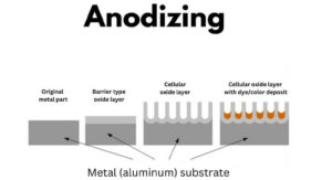
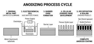
Yes. Anodizing changes the dimensions of an aluminum part, and the change is large enough to scrap a tight-tolerance feature if you ignore it. Anodizing is a conversion coating, not a paint layer, so the oxide grows both into and out of the aluminum surface. The accepted industry rule of thumb is the 50/50 rule: about 50% of the total coating thickness builds outward from the original surface, and 50% converts the existing metal below it (per MIL-A-8625, the governing US military spec). For a Type III hardcoat at 0.002 inches thick, that means roughly 0.001 inches of growth per surface, which adds about 0.002 inches across an outside diameter and removes about the same from a bore.
How much does anodizing change part size?
Anodizing changes each coated surface by roughly half the total coating thickness. The oxide layer is part metal conversion and part outward growth, so a 25 micron coating adds about 12 microns of buildup per surface while consuming about 12 microns of base aluminum below it (ASTM B244 covers how this thickness is measured). Across a diameter, where two surfaces face each other, the dimensional change is close to the full coating thickness.
This matters because the change scales with coating type. A decorative Type II finish moves a dimension by a few ten-thousandths of an inch, which most commercial tolerances absorb without trouble. A thick Type III hardcoat can move a critical fit by several thousandths, which is enough to seize a bearing bore or bind a sliding shaft.
Type I vs Type II vs Type III: which one changes dimensions the most?
Type III hardcoat changes dimensions the most because it produces the thickest oxide layer, typically 0.001 to 0.003 inches (25 to 75 microns) and sometimes thicker for wear applications. Type II is far thinner at 0.0002 to 0.001 inches (5 to 25 microns), and Type I chromic acid anodizing is the thinnest at roughly 0.00002 to 0.0001 inches, which is why aerospace shops reach for it on fatigue-critical and close-tolerance parts.
| Anodize Type | Process Acid | Typical Thickness | Approx. Change per Surface | Best Use |
| Type I | Chromic | 0.00002–0.0001 in (0.5–2.5 µm) | Negligible | Fatigue-critical, tight tolerance, paint base |
| Type II | Sulfuric | 0.0002–0.001 in (5–25 µm) | ~0.0001–0.0005 in | Decorative color, general corrosion resistance |
| Type III | Sulfuric, low temp | 0.001–0.003 in (25–75 µm) | ~0.0005–0.0015 in | Wear surfaces, dielectric, heavy duty |
Note: Thickness ranges per MIL-A-8625. Confirm exact buildup with your anodizer for the specific alloy and class.
The takeaway for a designer is simple: If a feature has a tolerance band tighter than the expected dimensional change, you have to plan for it at the machining stage, not after the parts come back from finishing.
How do I calculate dimensional growth before machining?
Start with the coating thickness your finish requires, then apply the 50/50 rule to each affected surface. If you specify a 0.002 inch Type III coating, expect about 0.001 inch of outward growth on every anodized surface. On an outside diameter that growth happens on both sides, so the OD increases by about 0.002 inch total. A bore shrinks by the same amount because the oxide grows inward toward the center.
The practical workflow at XC Machining is to machine the feature undersize on outside dimensions and oversize on internal dimensions by the calculated buildup, so the part lands in tolerance after anodizing. For a shaft that must finish at 0.5000 inch with a 0.002 inch hardcoat, we machine it to roughly 0.4980 inch before finishing. This pre-compensation only works when the drawing states whether the final dimension is before or after anodize, which is the single most common source of rejected parts we see.
How does anodizing affect holes, threads, and press fits?
Anodizing shrinks holes and tightens threads, which is why threaded features need special handling. The oxide grows inward on a hole, reducing the diameter by roughly the coating thickness across the bore. On a tapped hole, a Type III buildup can reduce thread clearance enough that a standard fastener no longer starts cleanly.
There are three reliable ways to protect threaded and precision features:
-
Tap after anodizing when the thread tolerance is critical, so the threads see no buildup.
-
Mask the feature so it stays bare, common for grounding points, press-fit bores, and electrical contacts.
-
Pre-compensate the machined size when masking is impractical, accepting the calculated growth.
Press fits deserve their own note. A bore that holds a bearing or dowel pin will tighten after anodizing, and the oxide layer is brittle, so an aggressive press can crack it. For an in-depth breakdown of calculations and prevention strategies for these tight assemblies, read our dedicated article on 6061 vs 6063 aluminum and mating structures. For bearing bores and slip fits, masking the bore or reaming after anodize is usually the safer route.
How do I call out anodizing on a drawing so dimensions hold?
State the anodize type, class, thickness, and whether dimensions apply before or after finishing. A complete callout reads something like "Anodize per MIL-A-8625 Type III Class 2, 0.002 inch thick, dimensions after anodize." That one line removes the guesswork that causes most finish-related rejects.
Three details make a callout bulletproof:
-
Type and class: Type defines the process, class defines color (Class 1 undyed, Class 2 dyed).
-
Thickness, with a tolerance: “0.002 inch” alone invites a range; “0.002 ± 0.0005 inch” controls the buildup.
-
Before or after anodize: This tells the machinist whether to pre-compensate and tells the inspector what to measure.
When using our precision CNC machining or milling setups, our automated DFM review flags any feature whose tolerance is tighter than the expected anodize buildup, usually within 12 hours of file upload, so the conflict gets resolved before a single chip is cut.
When should I choose Type I anodizing to protect tolerances?
Choose Type I chromic acid anodizing when dimensional change must be near zero or when the part is fatigue-critical. Because the coating is only about 0.00002 to 0.0001 inches thick, the dimensional impact is usually inside normal machining tolerance, so no pre-compensation is needed. Type I also does not reduce fatigue strength the way thicker coatings can, which is why it remains common on aircraft structural components—even though it offers less corrosion and wear protection than Type II or III.
The trade-off is protection. Type I gives the least corrosion resistance and cannot be dyed in the rich colors that Type II supports. If your part needs both tight tolerance and color, the better path is often utilizing Type II anodizing and surface finishing services on non-critical surfaces while keeping the precision features masked or finished after anodize. If you are comparing your mechanical options for structural applications before committing to a finish, see our comprehensive 7075 vs 6061 aluminum engineering comparison.
Frequently Asked Questions
How much does Type III hardcoat anodizing add to a dimension? Type III adds roughly half the coating thickness per surface. For a common 0.002 inch hardcoat, expect about 0.001 inch of growth per surface, or about 0.002 inch across a diameter, per the 50/50 rule in MIL-A-8625.
Does Type II anodizing change dimensions enough to matter? For most commercial tolerances, no. Type II coatings run 0.0002 to 0.001 inches thick, so the per-surface change is a few ten-thousandths of an inch. It matters only on features with tolerance bands tighter than about 0.0005 inch.
Should I anodize before or after tapping threads? For critical threads, tap after anodizing so the threads see no oxide buildup. For non-critical threads, you can tap first and accept the slight clearance reduction, or specify a class of fit that allows for it.
Can anodizing be removed to recover an out-of-tolerance part? Yes, anodizing can be stripped in a chemical bath, but stripping also removes a thin layer of base aluminum, so a re-anodized part is not always recoverable to the original dimension. It is cheaper to plan the buildup correctly the first time.
Which anodize type is best for press-fit bores? Type I or a masked bore. Press fits tighten after anodizing and the oxide is brittle, so the safest approach is to keep the bore bare with masking or finish it after anodize.
Does anodizing thickness vary by aluminum alloy? Yes. High-copper alloys like the 2000 series build thinner, less uniform coatings, and high-silicon alloys can show color variation and reduced thickness. Confirm achievable thickness with your anodizer for the specific alloy.
Sources
-
US Department of Defense, MIL-A-8625F, Anodic Coatings for Aluminum and Aluminum Alloys
-
ASTM B580, Standard Specification for Anodic Oxide Coatings on Aluminum
-
ASTM B244, Standard Test Method for Measurement of Thickness of Anodic Coatings on Aluminum
About the Author
The XC Machining Engineering Team produces high-precision components for aerospace, medical, and industrial customers, holding tolerances down to ±0.005 mm. This guide reflects production experience anodizing thousands of machined aluminum components. If you are developing a part requiring tight control over post-finish geometry, navigate to our core aluminum CNC machining interface or get a quote on anodized aluminum parts directly.