Skip to content
The pouring system refers to the flow passage before the plastic injection mold enters the mould cavity from the nozzle, including main flow passage, cold material cavity, diversion passage and gate. Formed parts refer to various parts forming the shape of the product, including moving die, fixed die and cavity, core, forming rod and exhaust port, etc.
Common Challenges in Plastic Injection Mold and How to Overcome Them
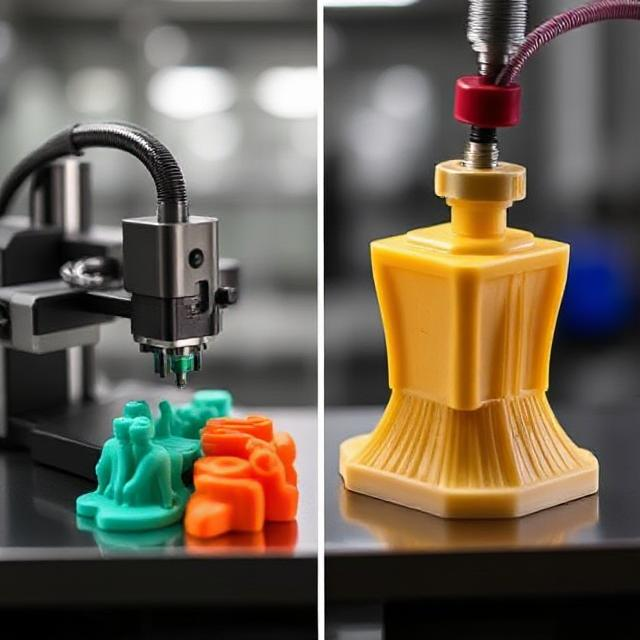
Plastic injection mold is a highly efficient and versatile manufacturing process, but it comes with its share of challenges that can impact quality, efficiency, and cost. From material selection to dealing with production defects like warping or sink marks, navigating these issues requires a combination of technical expertise and strategic problem-solving.

1. Main flow channel
It is a channel in the plastic injection mold that connects the injection nozzle to the runner or cavity. The top of the main runner is concave to facilitate connection with the nozzle. The inlet diameter of the main runner should be slightly larger than the nozzle diameter (0.8mm) to avoid overfilling and prevent blockage due to misalignment between the two. The inlet diameter depends on the size of the product and is typically 4-8mm. The diameter of the main runner should be expanded inward at an angle of 3° to 5° to facilitate the demolding of runner debris.
2. Cold material hole
It is a cavity located at the end of the main channel to trap the cold material generated between the two injections molding at the tip of the nozzle, thereby preventing the clogging of the branch channel or gate. If the cold material is mixed into the mold cavity, internal stress is easily generated in the manufactured product. The diameter of the cold material cavity is about 8-10mm and the depth is 6mm.
To facilitate demolding, the bottom is often supported by a demolding rod. The top of the demolding rod should be designed with a meandering hook shape or a recessed groove to facilitate the smooth extraction of the main runner debris during demolding.
3. Diversion channel
It is the channel connecting the main runner and each cavity in a multi-cavity mold. In order to ensure that the melt fills each cavity at a uniform rate, the arrangement of the branch runners on the mold should be symmetrical and equidistant.
The shape and size of the runner section have an impact on the flow of plastic injection mold melt, the demolding of products, and the ease of acrylic injection molding manufacturing. If the flow is equal to the amount of material, the circular section has the minimum resistance.

However, due to its small surface area and narrow length, cylindrical runners are not conducive to cooling debris in a diversion channel. Furthermore, such diversion channels must be opened on both halves of the plastic injection mold simultaneously for proper alignment; consequently trapezoidal or semicircular cross-section diversion channels with release levers are frequently employed as alternatives for easier alignment and cooling of debris in diversion channels.
To maximize flow resistance reduction and speed up filling speeds, runners must be polished on both their surface and inside walls in order to reduce flow resistance and speed filling times. Their size depends on the type of plastic injection mold material, product size and thickness; typically for thermoplastic materials this width does not exceed 8m, with maximums reaching 10-12m and minimums as low as 2-3m depending on needs; in order to meet them efficiently it should also aim at minimising cross-sectional area so as to avoid increasing diversion channel debris accumulation while simultaneously shortening cooling times and speeding cooling time by this means.
4. Gate
It is the channel connecting the main (or branch) channel and cavity, with its cross-sectional area equal to or reduced from that of its respective main channel or branch channel counterparts; therefore it has the smallest cross-sectional area within an overall runner system. Furthermore, shape and size of its gates have an enormous influence on product quality.

The role of the gate is: To control the flow speed
In plastic injection mold, the melt stored in this part may prematurely solidify, preventing backflow.
The melt passing through is subjected to strong shear to increase temperature, thereby reducing apparent viscosity, improving fluidity and facilitating the separation of the product from the runner system. The design of the gate shape, size, and location depends on the nature of the plastic, the size and structure of the product.
Cross-sectionally, gates tend to have rectangular or circular cross-sections with small cross-sectional areas and short lengths; this choice takes into account not only their intended effects, but also the fact that making small gates larger is easier than making larger ones smaller; similarly, gate location should generally be chosen where product thickness is thickest without altering appearance and its design should take into account properties of plastic melt. Finally, cavities serve as plastic injection mold spaces where plastic products can be formed into finished items.
Cross-sectionally, gates typically take the shape of rectangles or circles with small cross-sectional areas and short lengths; this choice takes into account not only aesthetic considerations but also practical reasons – making small gates larger is easier than making larger gates smaller; similarly, choosing to place gates where product thickness is greatest without adversely affecting appearance is generally advised while the size design must take into account properties of plastic melt used to form it into undercuts in molding cavities is key in creating quality plastic products.
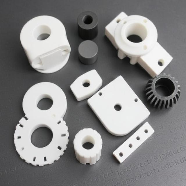
Molding parts refers to any components used to form cavities. Each plastic injection mold part often has a specific name: for instance, one that creates the outer shape of a product is called the female mold (also referred to as female molding), while those responsible for internal shapes (such as holes and slots) may be called core or male molds (sometimes also referred to as male molds). When designing plastic injection mold parts, their overall structure must first be determined based on factors like plastic properties, geometric shape of product design requirements, dimensional tolerances and usage requirements before final designs can begin.
Secondly, the selection of the parting surface, gate and vent position as well as the demolding method is based on the determined structure. Finally, the design of each part and the combination method between each part are determined according to the control product size.
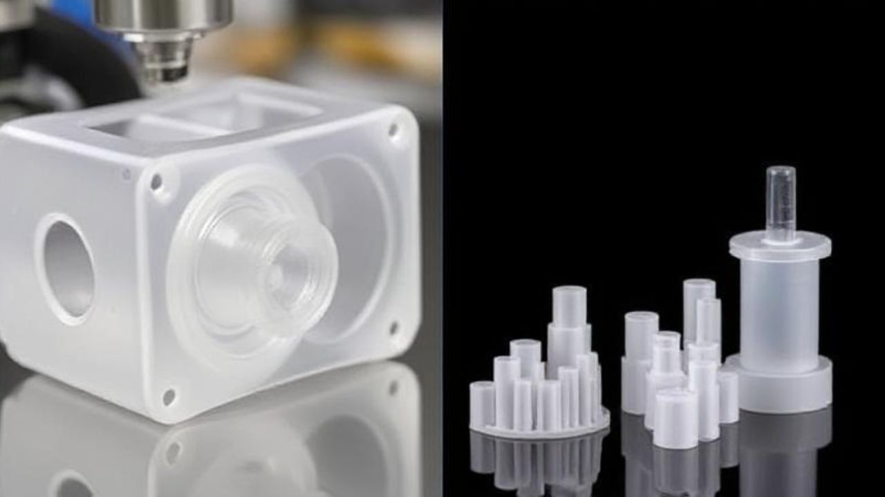
The plastic melt has a high pressure when entering the cavity, so the injection molded parts should be reasonably selected and checked for strength and rigidity. To ensure the smooth appearance and easy demolding of plastic products, the surfaces in contact with plastic should have a roughness Ra>0.32um and be corrosion resistant. The plastic injection mold parts are generally heat treated to increase hardness and made of corrosion-resistant steel.